Delta values for a range of die semi-angles and drawing reductions. Wire drawing equipment The wire is first passed through the overhead loop and pulley brought down and then inserted through the die of the second drum and drawn through this die for further reduction.

Die Science How To Perform A Draw Reduction
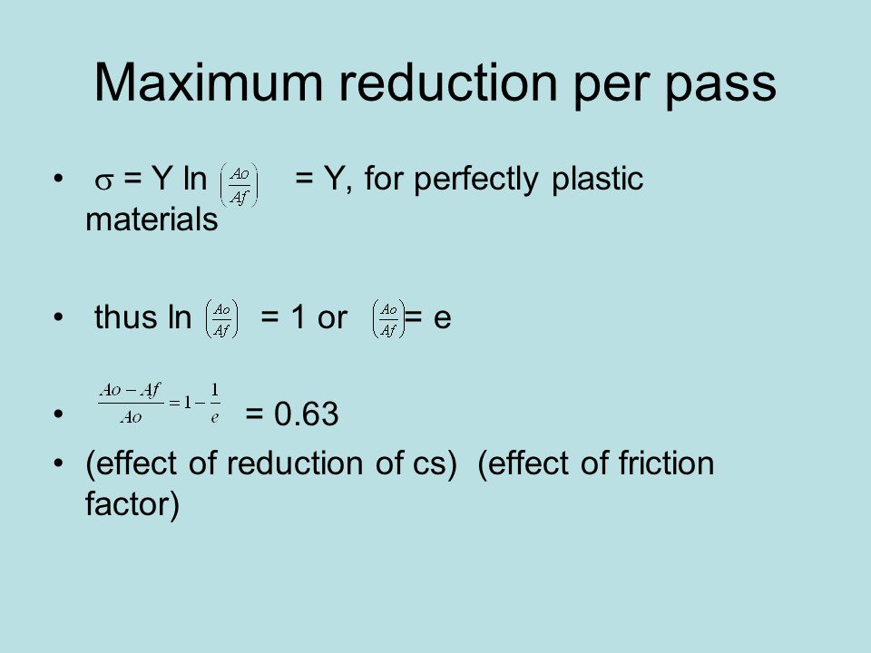
The ideal work derive an expression for the maximum reduction in area per pass for a wire drawing operation for a material with a true-stress strain curve of σKεn Total work Ideal work frictional work redundant work Total work Ideal work 02 x Ideal work 12 x Ideal work Or Total work of deformation 12 u x volume.
. By pulling a rod or wire through a die the cross section is reduced. L 1 l 0. Fig 1 Process of drawing.
The pulling force is limited by the strength of the material. Thus the wire is drawn through all the wire drawing drums of the set in a continuous manner to get the required finished diameter of the. This results in a stretching or elongation of the material along with a reduction in cross sectional area.
A die angle. Incoming wire diameter mm inch Øout. 1241 The ratio of draw stress to flow stress.
Having the right number of stations and the right diameters and heights is critical to the success of a multistage drawing process. N number of dies. The incoming wire diameter is calculated from the drawn wire diameter for a given area reduction by using.
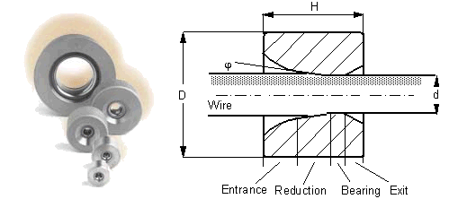
The approach angle where the actual reduction in diameter occurs giving the half die angle α The bearing region produces a frictional drag on the wire and also remove surface damage. Steel wire work hardens during plastic deformation and the ductility the degree of elasticity is reduced while the tensile strength increases. Wire chemistry approach angle lubrication drawing speed and reduction are the most significant.
The force needed to pull the wire through. The area reduction in small wires is generally 1525 and in larger wires is 2045. The incoming wire diameter is calculated from the drawn wire diameter for a given area reduction by using.
δ w Y l 0 l 1 d l l Y ln. If the size of the incoming wire is known. 104 shows the basic principle of the bundle wire drawing process.
The process of wire drawing changes material properties due to cold working. Wire area reduction percentage Inversely the drawn wire diameter is calculated from the incoming wire diameter. δ w Y δ l l.
AR reduction in area. Wire drawing consists of pulling a metal wire through a small circular opening called a die. In this process there is no force is applied for pushing the wire into the die from the entrance side.
Pull too hard and the metal will break. In the simplest concept of drawing a break occurs when the draw stress equals the yield andor breaking stress of the wire at the die exit. Wire area reduction percentage Inversely the drawn wire diameter is calculated from the incoming wire diameter.
Dl beginning wire diameter. Drawn wire diameter mm inch A. So if the bar extends from length l0 to l1 total work doneunit volume is.
Yielding and breaking are generally associated because of the instability created by the plastic stretching of the wire between dies. D wire diameter Dl beginning wire diameter Ds ending wire diameter AR reduction in area N number of dies Df finished diameter of the die Bl bearing length. The material should be sufficiently ductile since it is pulled by the tensile forces.
During drawing operation each time the wire goes trough a die. A draw reduction is a multistep process in which the surface area of the original blank is displaced through a series of drawing operations. Unknown Sides and Angles.
In products where subsequent draws are needed to reach the desired finish diameter an average area reduction per die of about 20-30 is usual. Uniform die wear and less wire breakage. Incoming wire diameter mm inch Øout.
The percentage reduction of area r is given by the following equation r 100 x Ao AfAo Where Ao is the initial area and Af is the final area of the wirerod after drawing. This can be applied to wire drawing. Drawn wire diameter mm inch A.
Wire drawing die Conical drawing die Shape of the bell causes hydrostatic pressure to increase and promotes the flow of lubricant into the die. The bundle wire drawing is another mechanical steel fiber production process where thousands of conventional drawn wires are bundled and drawn simultaneously 16The company NV Bekaert SA has an actual patent on this process. For initial passes fast rotating die boxes are used since the drawing speed is lower in these passes.
A draw reduction could involve two to 16 or more drawing operations. Use of rotating die boxes results in following advantages. Bl bearing length.
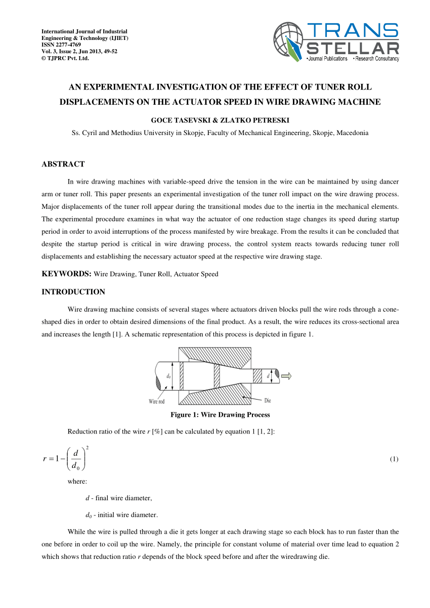
Wire drawing in brief. This reduction of section is at the same time balanced by. In wire drawing a tensile force is applied to the product rather than a compressive force applied to the billet such as in extrusion for example.
Avoidance of ovality in wire and capability to produce high accuracy wire. Both the diameter size and the section of the wire are reduced. As the area reduction changes so does the die sequence.
This increase is called Elongation. An increase of the wire length. Known Sides and Angles.
Step reduction drawing wire from d i-1 to d i 8 Examples drawing from step 3 to step 4. Refer to Page 301 Volume 1 Steel Wire Handbook Graph for Formula Four INCLUDING DIE ANGLE degrees Work Sheet for designing tooling geometry to prevent central bursting. The exact die sequence for a particular job is a function of area reduction input wire size and output wire size.
Having been an ISO 90012000 registered company for many years Fort Wayne Wire Die is. Elongation of wire drawing. Schematic of wire drawing process Some of the important terms associated with wire drawing are to be understood first.
Many of the technological. R 4 1-00900102 2 X 100 drawing 0102 wire to 090. In the first step the initial wires which can be wire rod are covered with a.
Df finished diameter of the die. The drawing of the wire starts with a rod or coil of hot rolled steel which is 08 to 16 mm larger than the final size required. Area reduction r is defined as Ao-AfAo -----21 The drawing ratio R is defined as AoAf 11-r -----22 The important parameters which affect the wire drawing force are the drawing ratio.
D wire diameter. Ds ending wire diameter. The primary emphasis in wire-drawing mechanics is on understanding and defining the relation-ships that exist between these process conditions and the resulting thermo-mechanical response of the wire.
WIRE DIE INDUSTRY LEADER As a worldwide industry leader Fort Wayne Wire Die Inc has taken great pride for more than 70 years in manufacturing quality precision-made wire drawing dies and hard-material components for the wire industry.
Wire Drawing Process Reduction Ratio Of The Wire R Can Be Download Scientific Diagram
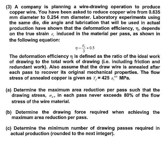
Solved Wire Company Is Planning A Wire Drawing Operation Chegg Com
Wire And Rod Drawing Ppt Video Online Download
Why Do We Say That Maximum Reduction 63 Occurs In Wire Drawing When The Tensile Strength Is Equal To The Yield Strength When Plastic Deformation Just Begins At Yield Strength More Deformation
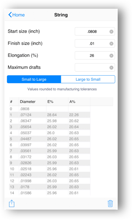
Eddie Wire Solutions Software Esteves Group
Wire Drawing

Die Science How To Perform A Draw Reduction
Wire Drawing Process Reduction Ratio Of The Wire R Can Be Download Scientific Diagram
0 comments
Post a Comment